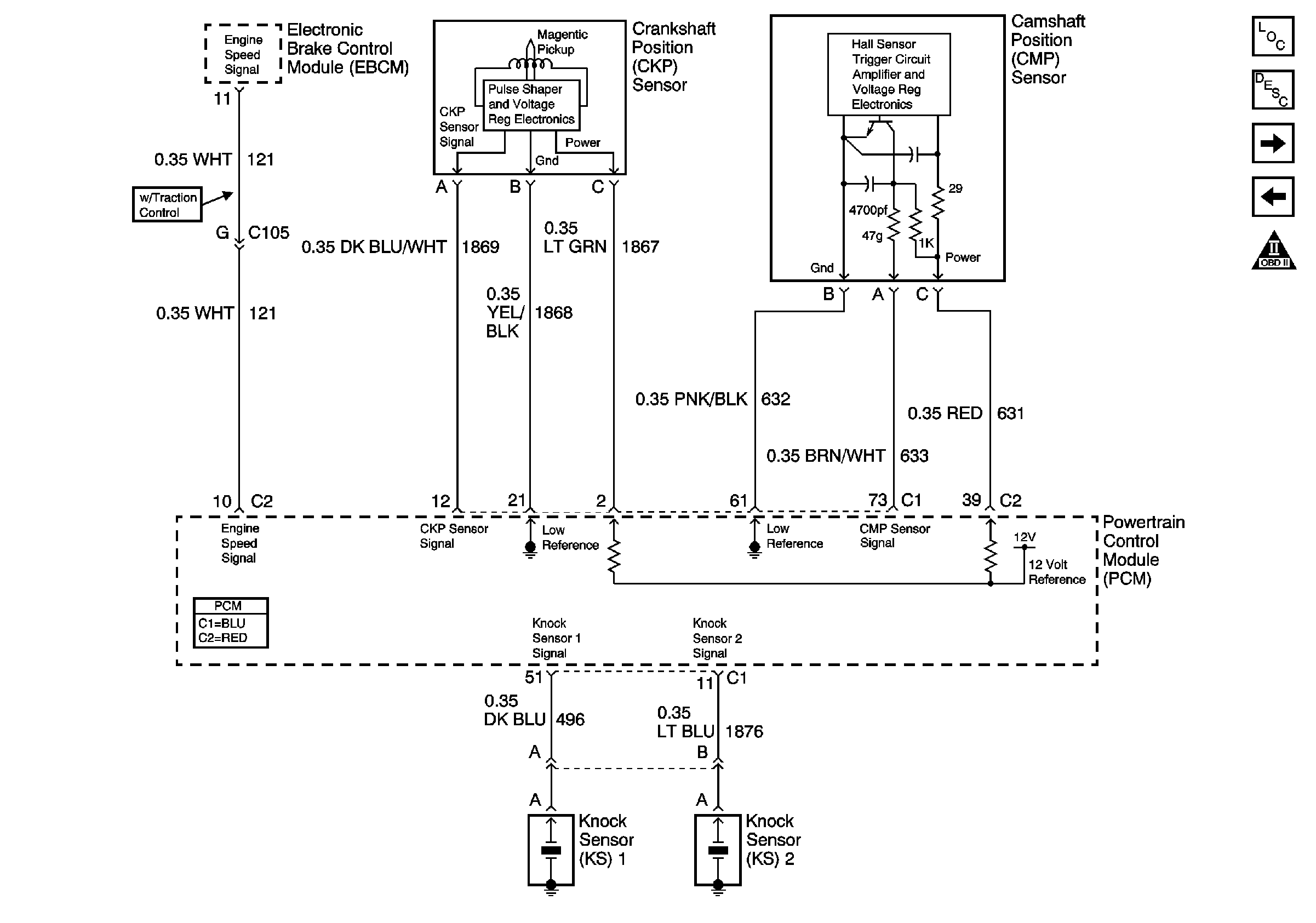
3 Wire Coolant Temperature Sensor Wiring Diagram

nest Hello Wiring Diagram, Nest Hello Advanced Wiring Diagram, 6.25 MB, 04:33, 63,749, gt8monster, 2018-06-16T10:14:46.000000Z, 19, Nest Hello Doorbell: 18 Questions/Answers You Need To Know - Smart Home Point, www.smarthomepoint.com, 1057 x 852, png, nest diagram hello doorbell wiring google camera chimes chime install multiple lh4 googleusercontent answers questions know need pre, 20, %ef%bb%bfnest-hello-wiring-diagram, Anime Arts
Coolant temperature sensor wiring diagram. 3 wire ect diagram. The signal from the sensor is shown and can be downloaded. When the engine cools, the contacts on the fan relay switch open, and the fan stops automatically.
Intake air temperature (iat) sensor wiring diagram. An intake air temperature sensor or iat sensor has the following two wires. The iat sensor has two wires, which come from the ecu. A positive current is supplied from the ecu to the iat sensor and goes back through the ground wire. Connect both wires to the connecting terminals of the ect sensor and measure the resistance. Then start the car's engine. Set the car to neutral and put the car on parking brakes. 5 volt reference wire ground wire earth signal wire for cluster mounted temperature gauge 3 wire coolant temperature sensor wiring diagram.
3 wire Temp sensor? & other - Third Generation F-Body Message Boards

Repair Guides
Repair Guides
RaceCapturePro installation guide - Autosport Labs
Code 15 - Coolant Temperature Sensor Circuit
Coolant Temperature Sensor Wiring Diagram - Hanenhuusholli
Ls1 Coolant Temp Sensor Wiring Diagram - Diagram For You
Ls1 Coolant Temp Sensor Wiring Diagram - Free Diagram For Student

Ls1 Coolant Temp Sensor Wiring Diagram - Free Wiring Diagram
