Vfd Control Circuit Diagram
The three major sections of the controller are as follows: Variable frequency drive (vfd) mainly has a rectifier, intermediate circuit, and inverter to convert back dc voltage into ac as shown in the block diagram.
The vfd has to run between 20 hz (say lf) and 50hz (say hf).

Vfd control circuit diagram. Vfd start stop wiring diagram: Induce harmonic distortion on the incoming supply lines. These sections include the power conversion area.
Vfd start stop wiring diagram electrical4u. After making use of the dc bus voltage across the igbts (without the motor attached) regulate the pwm 1k preset until the voltage across the rails turn out to be equivalent to the meant motor voltage features. The control section of the microprocessor is responsible for the control of the vfd operations.
It might be carried out according to the following directions: Vfd motor control circuit diagram pdf. 1 the vfd s three phase ac input terminals r l1 s l2 t l3 the power line s input terminals connect to 3 phase ac power through line protection or leakage protection breaker it does not need to consider the connection of phase sequence.
This is a basic circuit block diagram of a three phase vfd. 3 phase induction motor speed controller circuit homemade circuit projects motor speed electronic circuit projects electronic schematics how to control vfd with push button switch terminal control wire control youtube electrical circuit diagram control wire variable frequency drive vfd system need working benefits variables frequencies driving hip4086. The 1k preset shown in the diagram is the rms control knob, which may be appropriately adjusted for acquiring the desired proportionate amount of output voltage in the form of pwms at pin3 of ic2 for further processing.
The diodes d1, d2, and d3 are connected with the positive rail and the diode d4, d5 and d6 are connected with the negative rail. Rectifier section of vfd circuit rectifier section uses 6 diodes. •energy savings using a vfd to control the speed of a constant torque load is a direct function of speed reduction.
Vfd start stop wiring diagram. Another aspect is the size of vfd. Vfd wiring diagram showing power in start stop control with plc using ladder logic controlling vfds manual inputs file jpg probotix allen bradley powerflex 3 phase induction motor and the main circuit saftronics s10 basic delta b series standard how to read a variable frequency drive for constant 525.
K1 no1, pb3, pb4, pb5 should be of potential free contact. The time to increase from lf to hf is variable depending the application (up to minutes). Connect or do wiring as per vfd side drawing, you take +24 v from the vfd pcb directly.
(1) the vfd's three phase ac input terminals (r/l1, s/l2, t/l3) the power line's input terminals connect to 3 phase ac power through line protection or leakage protection breaker, it does not. Block diagram of vfd a variable frequency drive (vfd) is a type of motor speed controller that drives an induction motor by varying the frequency and voltage supplied to the electric motor. Drives as power quality problem sources 1.
Also the value of lf may be variable. This is set to produce a corresponding output that may be equivalent to the mains 220v or 120v ac rms. Variable torque loads • require much lower torque &.
The power consumption section changes the ac voltage to dc. The vfd main circuit terminals shown as below figure. Tips on how to establish the suggested 3 phase vfd circuit.
Vfd working & block diagram a variable frequency drive controls the speed, torque, and direction of an ac induction motor. As the frequency of the voltage is reduced, the inductive reactance of the motor stator winding is also reduced. The vfd control (time to increase the frequency)will be made by an arduino nano.
It takes fixed voltage and frequency from ac input and converts it to a variable voltage and frequency ac output. A simplified vfd working principle diagram is shown in below. When you press the on push k1 contactor will hold and k1 no1 become nc.

Delta Vfd L User Manual Pdf amitree
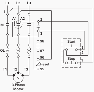
motor control circuit diagram pdf IOT Wiring Diagram

Vfd Wiring Diagram / Plc Vfd Wiring Diagram Diagram Base

Inverter Drive Motor Connection Home Wiring Diagram
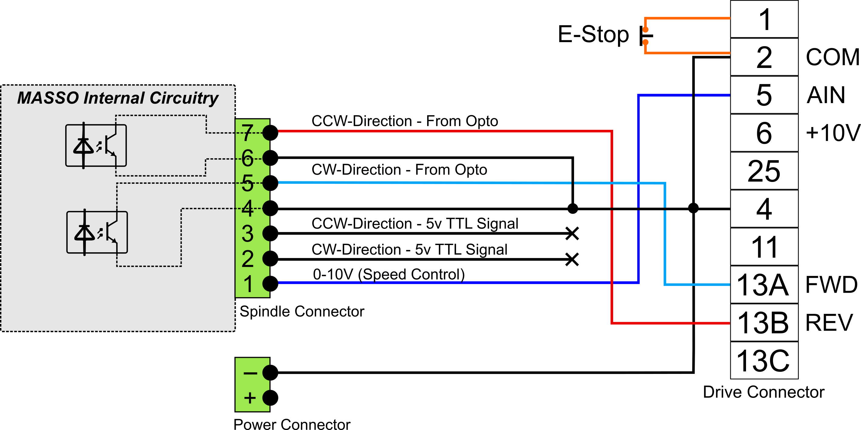
Wiring Vfd Motor Control Circuit Diagram Wiring Diagram

Single Phase Variable Frequency Drive VFD Circuit
15 Vfd Circuit Diagram Robhosking Diagram

Wiring Vfd Motor Control Circuit Diagram / VFD switch box
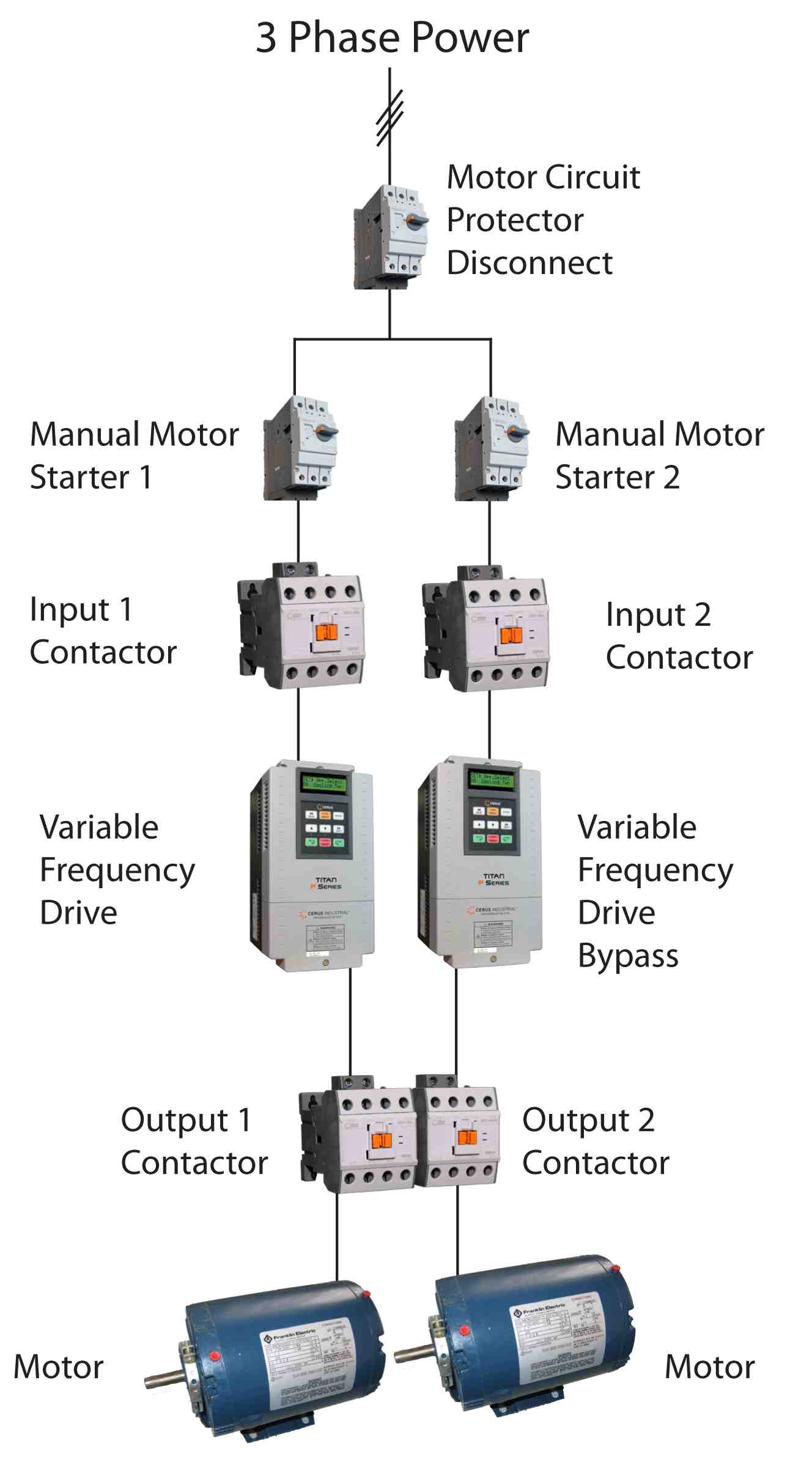
wiring diagram for vfd Wiring Diagram and Schematic

Single Phase Variable Frequency Drive VFD Circuit

Contactor Vfd Motor Control Circuit Diagram SATANDOLL
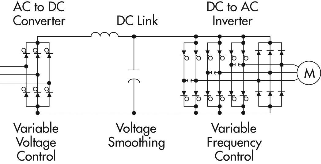
3 Phase Induction Motor Driver Vfd Motor Control Circuit
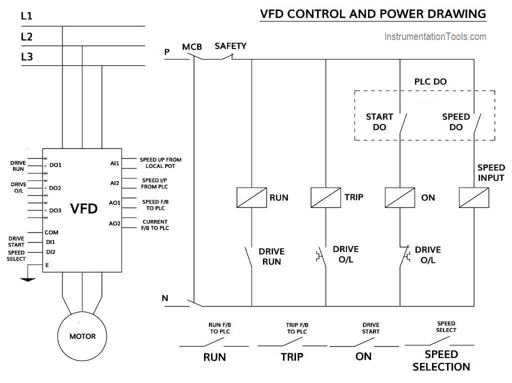
How to Control VFD with PLC using Ladder Logic

Wiring Vfd Motor Control Circuit Diagram Vfd Motor

Vfd Panel Wiring Diagram Switch Wiring Diagram
