Vfd Connection Diagram
Categories wiring diagram tags connection. (1) the vfd's three phase ac input terminals (r/l1, s/l2, t/l3) the power line's input terminals connect to 3 phase ac power through line protection or leakage protection breaker, it does not need to consider the connection of phase sequence.

Controlling a VFD with Snap Pac Products OptoForums
343 wire size 19 344 wire type rating.

Vfd connection diagram. What is ac drive working types of electrical drives vfd electrical circuit diagram electrical diagram diagram. Delta el series vfd 3 wire connection join our new batches of plc and scada for more visit www autoneticstraining com nashik automation train. Rectifier section of vfd circuit rectifier section uses 6 diodes.
Vfd start stop wiring diagram: See table 12 for their functions. Vfd start stop wiring diagram.
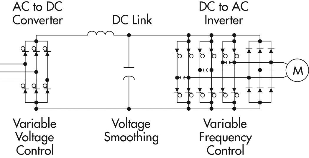
This is a basic circuit block diagram of a three phase vfd. Start and stop through digital input di1. Danfoss vfd control wiring diagram.
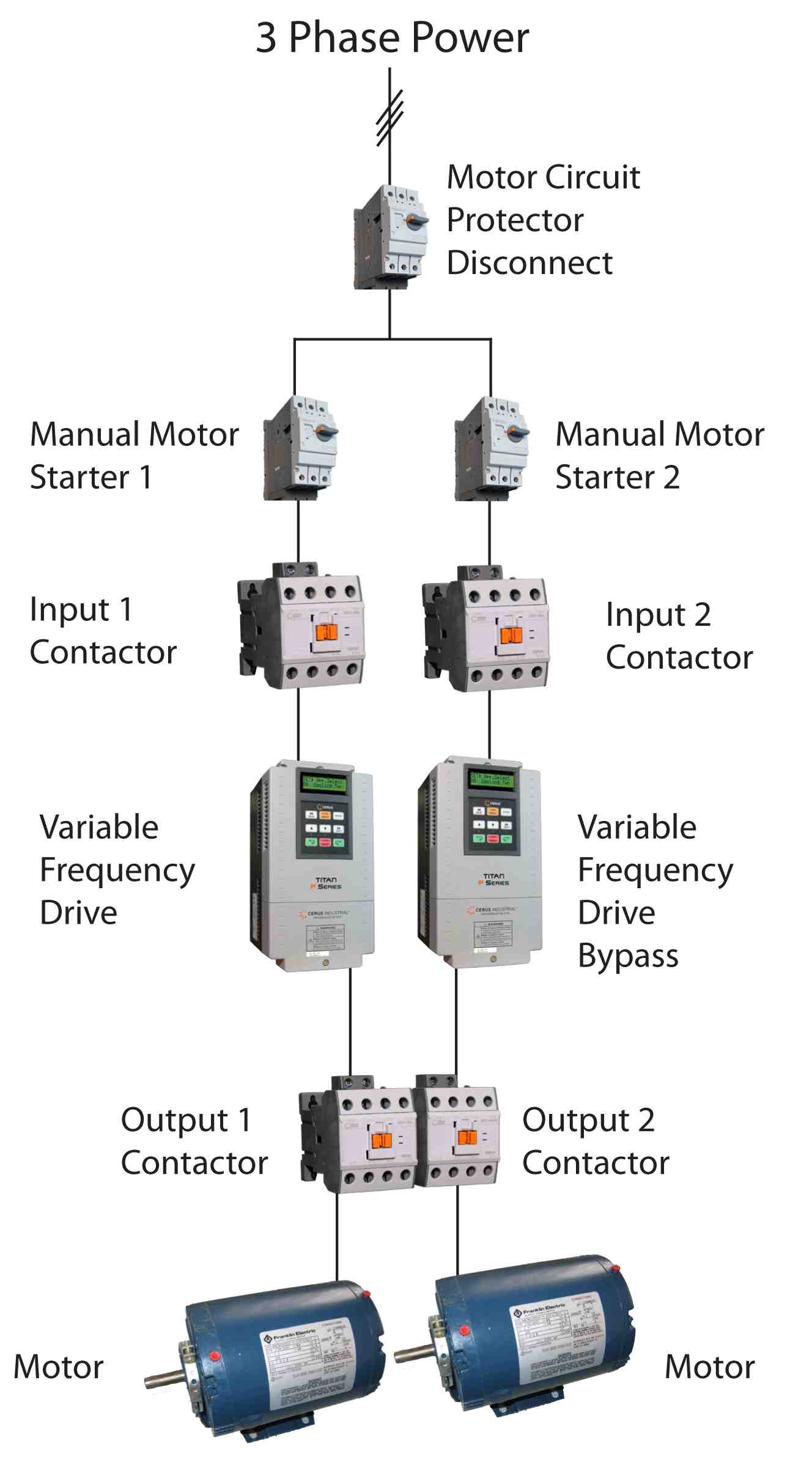
In bypass the motor is operated directly from line input power. Connect or do wiring as per vfd side drawing. Variable frequency drivevfd mainly has a rectifier intermediate circuit and inverter to convert back dc voltage into ac as shown in the block diagram.
Connection diagrams or wiring diagrams show the components of the control circuit in a semblance of their actual physical locations. A simplified vfd working principle diagram is shown in below. For speed increment when you enabling digital input the reference value (set value or your speed requirement) increases and.
Controlled environment that is suitable for the selected enclosure. On abb vfd control wiring diagram. Vfd control wiring with diagram | vfd wiring diagram | vfd motor control wiringin this video you will learn about vfd control wiring with diagram | vfd wirin.
Monitoring danfoss vfd in bypass october 04. This diagram shows the wires that supply power to the vfd, the wires that provide voltage from the vfd to the motor, and all the necessary input and output signals that the vfd needs for operation. Danfoss vfd with bypass wiring diagram.
Learn the basic wiring of variable frequency drives vfd with our electrician steve quist. A variable frequency drive regulates the speed and operation of an electric motors. The three major sections of the controller are as follows:
Vfd wiring system considerations when looking at a vfd wiring system there are several aspects that need to be consider due to interaction between various wiring in the system itself. 1 the vfd s three phase ac input terminals r l1 s l2 t l3 the power line s input terminals connect to 3 phase ac power through line protection or leakage protection breaker it does not need to consider the connection of phase sequence. A wiring diagram is a kind of schematic which uses abstract pictorial symbols to demonstrate every one of the interconnections of components inside a system.
Use the following chart to interpret the type code found on the and control wiring. Connect or do wiring as per vfd side drawing, you take +24 v from the vfd pcb directly. Variable frequency drive vfd is an electrical device by which we can vary the frequency of an ac power supply.
Recommended vfd cable installation guide 1 introduction: Vfd start stop through dcs remote local: You can perform all kind of action start, stop, speed increment, speed decrement and fault reset.
The diodes d1, d2, and d3 are connected with the positive rail and the diode d4, d5 and d6 are connected with the negative rail. Abb vfd control wiring diagram. Measure the length of the cable for jacket removal
K1 no1, pb3, pb4, pb5 should be of potential free contact. Unarmored vfd cable motor connection u2 v2 w2 x3 metallic conduit heatsink gnd u1 v1 w1 3 motor power u1 v1 w1 l1 metallic conduit x1 l2 l3. Danfoss vfd wiring diagram wiring diagram data schema pioneer avic n1 wiring diagram.
When you press the on push k1 contactor will hold and k1 no1 become nc. Vfd installation instructions the block diagram below shows a typical vfd installation. Shawcor has developed 600v, 1000v,.
This diagram shows the wires that supply power to the vfd, the wires that provide voltage from the vfd to the motor, and all the necessary input and output signals that the vfd needs for operation. The vfd main circuit terminals shown as below figure. Electromagnetic interference (emi) can be carried on the ground back to the drive via the ground connection shown above.
The vfds showed in the video are the d720s 230v single phase and the d720 230v three phase.

48 star delta with vfd diagram Wiring Diagram Harness Info

Wiring Vfd Motor Control Circuit Diagram Vfd Motor

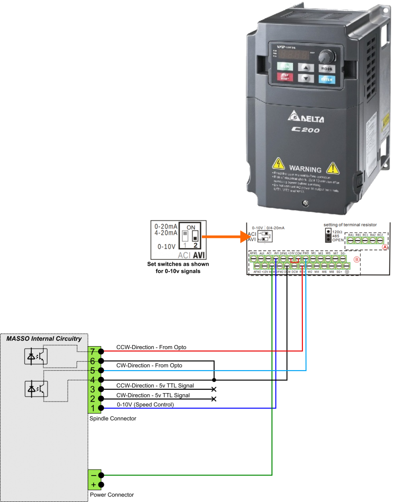
Connection diagram for CSMIO/IPM and DELTA VFD L series

Wiring Vfd Motor Control Circuit Diagram Wiring Diagram

Controlling the VFD This Old Mill

Vfd Panel Wiring Diagram Free Wiring Diagram

Consulting Specifying Engineer Web exclusive VFD

Vfd Starter Wiring Diagram / Diagram Allen Dley Vfd Wiring

Vfd Starter Wiring Diagram Wiring Diagram For Inverter

Principles of Operation AC VFD Drives

Delta Vfd L User Manual Pdf amitree

PLC Drive/VFD Control AutomationPrimer

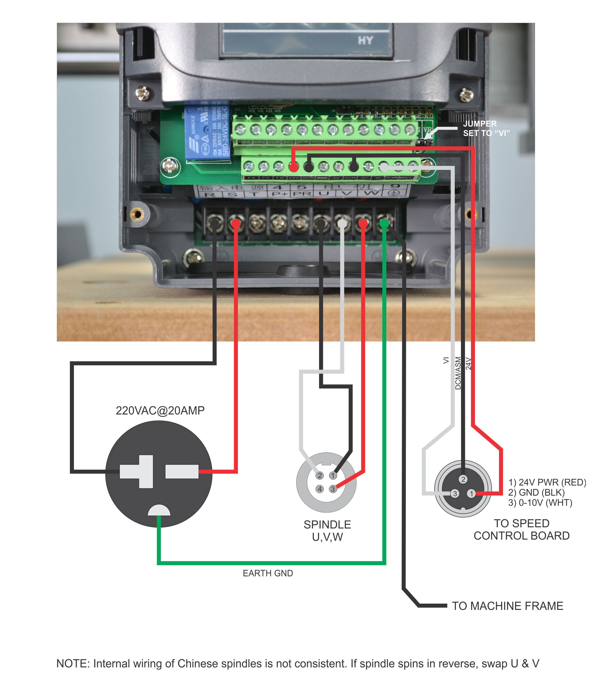
FileVFD wiring diagram.jpg PROBOTIX wiki
